![]()
Rear Wheel/Drive Assembly
| This site is designed to help you build your own go-kart. It will break down a go-kart into four sections: rear wheel/drive assembly, front wheel/steering assembly, braking system, and the throttle system. Each section will describe in general how the system works, and then specific parts will be given as examples of possible ways to build your go-kart. The advantages and disadvantages of the different systems will be discussed throughout this site. Please read and understand this entire site before deciding which plan is best for you. | ||
| To make your go-kart move, you need to transfer the power from the engine to the rear wheels on your go-kart. This can be done with either a belt and pulley system (torque converter kit #1377) or a chain and sprocket system. The chain and sprocket system will be used for explanation in this site, but the information can easily be transferred to a belt drive system. However, if you choose to use the torque converter kit note that if requires a #35 chain. The plans discussed in this site use a #41 chain. | ||
| If you choose to modify the plans given throughout this site, be aware of the chain size your sprockets need, the shaft and axle diameters, bore sizes, keyway sizes, and bolt hole patterns and make sure they all fit together. | ||
| An engine provides the power to move your go-kart. Table 1 along with Figure 1 show the parts that are needed to complete the go-kart plans described in the second half of this booklet. Table 2 along with Figure 2 describe an alternative system that can wore with up to an 8 horsepower (HP) engine. Mounted to your engine shaft is a clutch. A clutch prevents the engine from stalling by allowing if to achieve a high enough speed (usually about 2100 rpm) before engaging the load. The sprocket on the clutch can be connected by chain directly to the rear axle (drive) sprocket if your engine is positioned so the two sprockets line up. You also want to be aware of the clutch-to-rear axle sprocket ratio. A good ratio for 5 HP engines is 1:6. For example if you have a 10 tooth clutch driving a 60 tooth sprocket then you get a ratio of 1:6 (10/60:1/6). If you are making a larger go-kart, a 1:10 ratio may be desirable. If the clutch and rear axle sprockets do not line up, or if these ratios can not be obtained, you must use a jack shaft. | ||
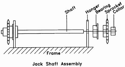
| A jack shaft serves two purposes: it transfers the engine's power horizontally so it can be distributed to the rear axle sprocket, and it provides another gear reduction to get to the optimal ratio as described above. One sprocket on the jack shaft lines up with the sprocket on the clutch, the other jack shaft sprocket lines up with the rear axle sprocket. When choosing sprockets, be sure your sprocket fits the chain size you are using. For example, in figure 2, a #35 chain is used and all sprockets fit a #35 chain. To calculate the overall ratio obtained by the jack shaft use this formula: | ||
| (A/B) X (C/D) : Overall Ratio A = Engine (clutch) Sprocket Teeth B = Input Sprocket Teeth on Jack Shaft C = Output Sprocket Teeth on Jack Shaft D = Axle Sprocket Teeth |
 |
|
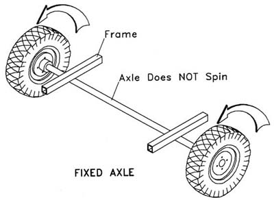
| Your rear wheels can be mounted in one of two ways, either on a fixed axle or on a live axle. | ||
| Fixed Axle A fixed axle is mounted firmly to the frame so that the axle itself does not spin. In the go-kart plans at the end of this booklet, the axle is welded to the frame. When a fixed axle is used, the wheels must be able to spin on the axle, and therefore, need to have bearings built into the wheel hubs. The drive sprocket and brake drum are then mounted to the wheel so that the whole wheel assembly spins together on the axle. |
|
|
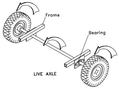
| Live Axle A live axle has the wheels, drive sprocket and brake drum mounted firmly to the axle, and the whole axle assembly then spins together. Bearings are attached to the frame, and the whole axle assembly spins on those bearings. However, since both wheels are attached to the axle, they rotate at the same speed which makes turning on pavement very difficult. Therefore, it is recommended that a live axle be used for off-road use only. |
|
|
| Another factor to consider when designing your go-kart is the speed and takeoff power you want your go-kart to have. The speed and takeoff power are determined by both the engine and the gearing, or sprockets, used. | ||
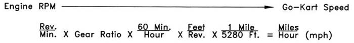
| Most engines run at a speed of 5600 rpm (revolutions per minute) when there is no load on the engine shaft. However, when the engine shaft is coupled to any load, the engine speed decreases. The larger the load, the greater the decrease. An engine with more horsepower will be affected less by the load, and therefore, be able to operate at a higher rpm. To figure out miles per hour (mph) from rpm, do as follows: | ||
 |
||
| Gear
Ratio: As discussed on page 1 of this booklet, the gear ratio con be found by dividing the number of teeth on your clutch by the number of teeth on on the drive sprocket. If using o jack shaft you have to perform this step twice; multiplying the two ratios together (see bottom of page 1). NOTE: The sprocket diameter con be used in place of the number of teeth on the sprocket far this calculation. |
||
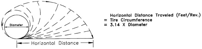
|
Feet/Rev. Ratio: Every time the wheel an your go-kart rotates, you travel the same distance as the circumference of your tire. Measure your tire diameter in inches and divide by 12 to convert it into feet. |
||
 |
||
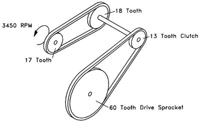
| Example: 17 tooth clutch driving a 18 tooth jack shaft sprocket. 13 tooth jack shaft sprocket driving a 60 tooth drive sprocket. 18 inch diameter tire. Engine operating with load at , 5450 rpm. |
||
 |
||
|
|
||
|
The formula from the previous page will give you the approximate top end speed of your go-kart, but it does not determine the take off speed or power your go-kart will have. A drive sprocket with a larger diameter and more teeth will fake off faster and have more power, but will reach a slower top end speed. A drive sprocket with with a smaller diameter and fewer teeth will take off slowly, but reach a faster top end speed. A smaller sprocket is closer to the size of the clutch sprocket, and therefore, rotates closer to the same speed as the engine. Decide whether speed or power is more Important to you, and choose your gearing accordingly. However, remember to use the gear ratio guidelines discussed on this page. Figures 1 and 2 show two examples of drive assemblies with a choice of three different engines. If you choose to modify these assemblies to fit your individual needs, always be aware of the chain size your sprockets need, the shaft and axle diameters, bore sizes, keyway sizes, and bolt hole patterns and make sure they all fit together. |
||
||
Main Home Page
||
Home Page
||
Rear Wheel/Drive Assembly
||
Front Wheel/Steering Assembly
||
Braking System
||
||
Throttle System
||
Frame
||
Engine Mount
||
Seat
||
Material List
||
Assembly Instructions
||
Before Using
||
||
Speed Calculator
||
© 2000 BuildYourOwnGoKart.com